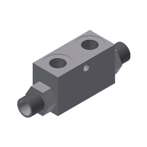
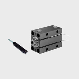
The valves for the compact hydraulic cylinders must be applied in order to control the amount of oil that is released during the various working phases of the machine.
Click to see the table:
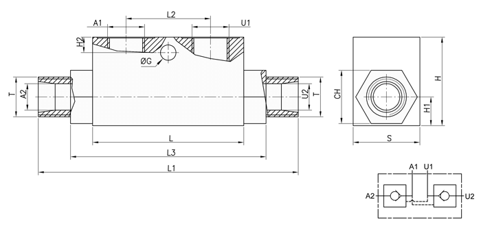
Valve table VRDE-AZ FF
Type | A1-U1 BSP | A2 - U2 | T | Q MAX L/min | P MAX bar | PILOT RATIO | L MAX | L1 | L2 | L3 | Ø G | H2 | CH | H1 | H | S | kg |
VRDE-AZ 010 FF | 1/4" | Ø12 | M18x1,5 | 30 | 350 | 1:4,5 | 68 | 138 | 38 | 86 | 7 | 7 | 24 | 13 | 40 | 30 | 0,67 |
VRDE-AZ 015 FF | 3/8" | Ø12 | M18x1,5 | 30 | 350 | 1:4,5 | 68 | 138 | 38 | 86 | 7 | 7 | 24 | 13 | 40 | 30 | 0,66 |
VRDE-AZ 020 FF | 3/8" | Ø15 | M22x1,5 | 50 | 300 | 1:4 | 80 | 166 | 40 | 108 | 8,5 | 15 | 27 | 16 | 50 | 30 | 0,97 |
VRDE-AZ 025 FF | 1/2" | Ø15 | M22x1,5 | 50 | 300 | 1:4 | 80 | 166 | 40 | 108 | 8,5 | 15 | 27 | 16 | 50 | 30 | 0,91 |
VRDE-AZ 030 FF | 1/2" | Ø18 | M26x1,5 | 80 | 300 | 1:4 | 90 | 180 | 40 | 133 | 8,5 | 15 | 30 | 20 | 60 | 40 | 1,67 |
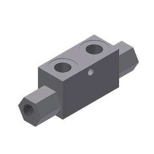
Click to see the table:
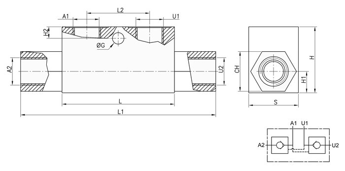
Valve table VRDE-F FF
Type | A1-U1 BSP | A1-U2 BSP | Q MAX L/min | P MAX bar | PILOT RATIO | L MAX | L1 | L2 | Ø G | H2 | CH | H1 | H | S | kg |
VRDE-F 005 FF | 1/8" | 1/8" | 20 | 350 | 1:4 | 53 | 86 | 20 | - | - | 17 | 11 | 30 | 20 | 0,3 |
VRDE-F 010 FF | 1/4" | 1/4" | 30 | 350 | 1:4,5 | 68 | 118 | 38 | 7 | 7 | 24 | 13 | 40 | 30 | 0,69 |
VRDE-F 015 FF | 3/8" | 3/8" | 30 | 350 | 1:4,5 | 68 | 118 | 38 | 7 | 7 | 24 | 13 | 40 | 30 | 0,64 |
VRDE-F 020 FF | 3/8" | 3/8" | 30 | 300 | 1:4 | 80 | 144 | 40 | 8,5 | 15 | 27 | 16 | 50 | 30 | 0,98 |
VRDE-F 025 FF | 1/2" | 1/2" | 50 | 300 | 1:4 | 80 | 144 | 40 | 8,5 | 15 | 27 | 16 | 50 | 30 | 0,91 |
VRDE-F 030 FF | 1/2" | 1/2" | 80 | 300 | 1:4 | 90 | 171 | 40 | 8,5 | 15 | 30 | 20 | 60 | 40 | 1,72 |
VRDE-F 040 FF | 3/4" | 3/4" | 120 | 300 | 1:4 | 107 | 196 | 60 | 8,5 | 16 | 41 | 23 | 70 | 50 | 3,11 |